Sunswift Racing: MPPT Project
The Sunswift Racing electric vehicle is an innovative project developed by a team of students from the University of New South Wales (UNSW). This vehicle not only set a Guinness World Record in 2022 but also won the 2023 Bridgestone World Solar Challenge, showcasing the incredible capabilities of solar-powered vehicles.

My Role
As the Project Lead for the Energy Systems Department, I was responsible for overseeing the development of the Maximum Power Point Tracking (MPPT) system. MPPT is a system that dynamically tracks and maximizes the power output from solar panels by adjusting their electrical operating point with changes in sunlight or temperature, playing a major role in the vehicle's performance and energy efficiency. This technology was crucial in optimizing the energy generated by the solar panels, ensuring that the vehicle could operate at peak efficiency throughout the race. My role involved leading the MPPT project, integrating it into the vehicle's energy control system, and ensuring that it maximized the energy efficiency of the solar panels.

MPPT PCB
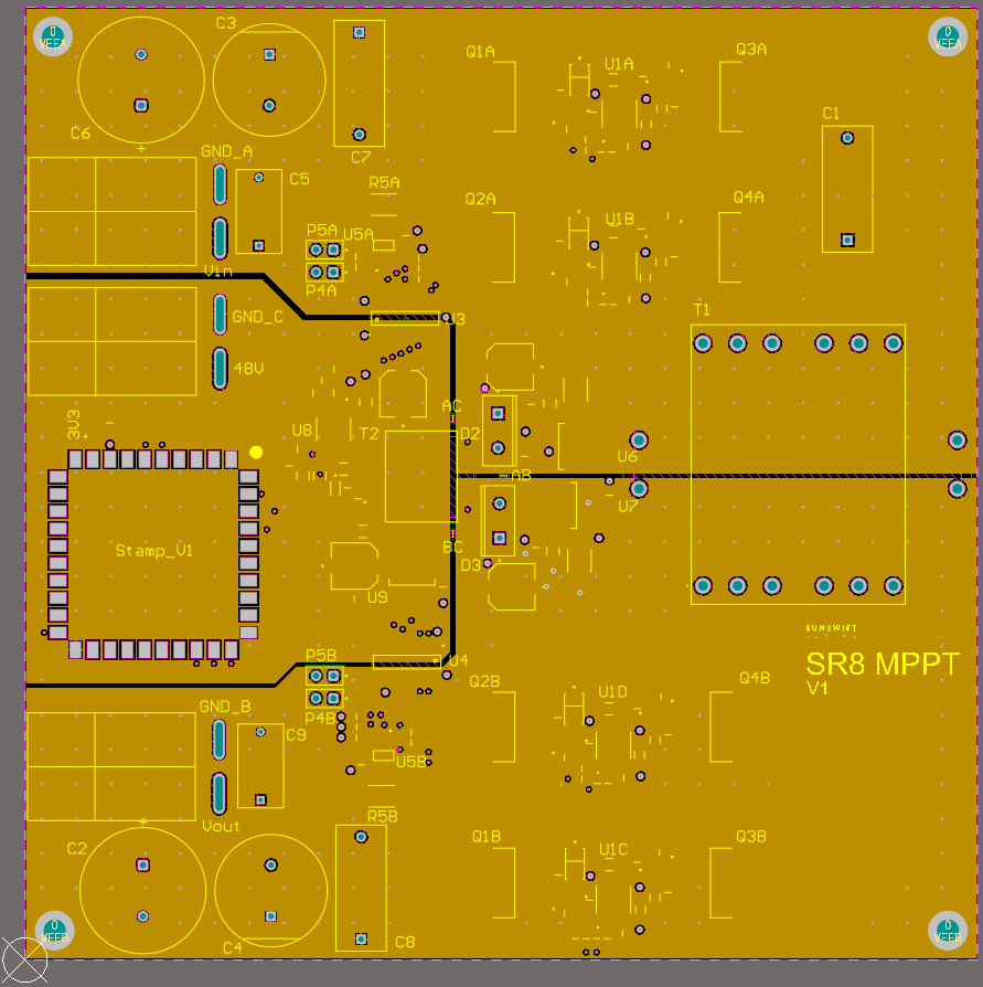
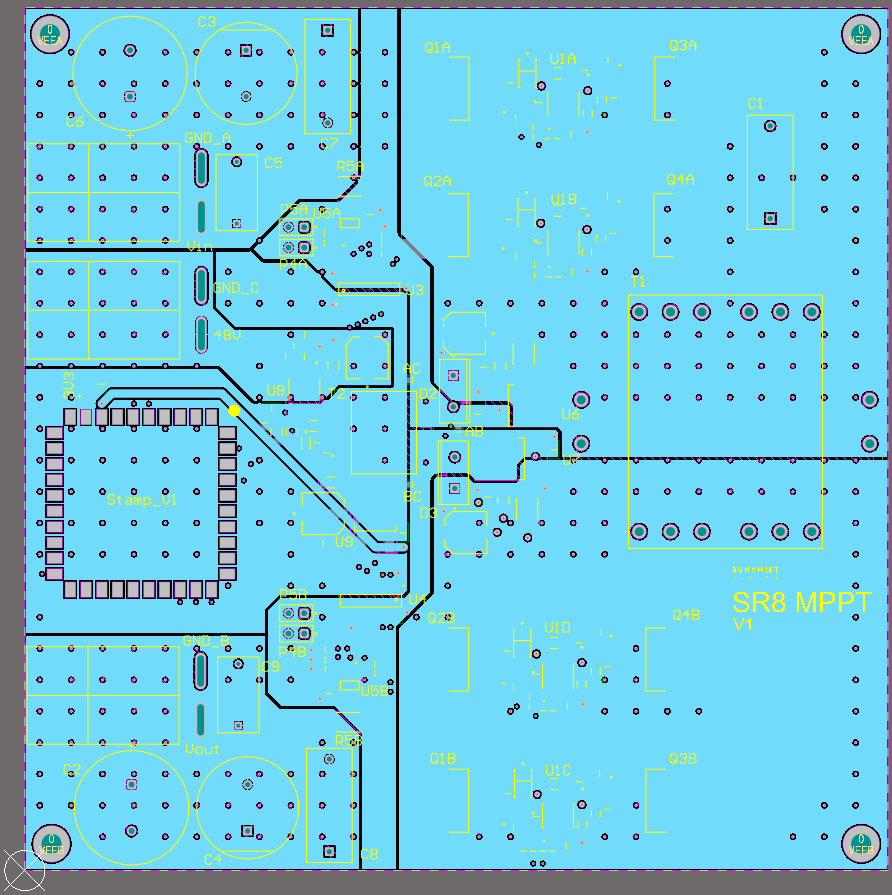
The MPPT PCB board features an isolated H-bridge boost converter and an STM32 microcontroller, designed to execute the dynamic tracking algorithm. The H-bridge boost converter efficiently adjusts the voltage to match the optimal power point of the solar panels, while the STM32 microcontroller handles the real-time calculations and decision-making for tracking changes in sunlight and temperature. This is a mixed-signal design, combining analogue current sensing with digital microcontroller circuitry along with switching power electronics. Separate grounding techniques are used to minimize noise interference between the analogue and digital sections, ensuring accurate measurements and stable operation.

This is a 4-layer PCB designed in Altium Designer, capable of supplying up to 1kW of power to the load. The design uses separate grounding techniques to minimize noise interference between the analogue and digital sections, ensuring accurate measurements and stable operation. The board's 4-layer structure improves power delivery and signal integrity by dedicating one layer to the power plane and another to the ground plane, reducing voltage ripple and ensuring stable operation under high load conditions. The outer layers handle signal routing and component placement, while the inner layers provide a low-impedance path for both power and ground, crucial for maintaining performance in high-power applications.
I have attached the full schematic diagram and the Altium Draftsman files below, which include detailed layout designs, component annotations, BOM, layer stack management, and more.


